8051 IO Mapped interface details
Overview
This is the simplest method of attaching the cs8900 to a cpu.
No GAL is used in this design. The GAL pins are cross
connected as shown below. This cross connection allows all 6 control
inputs and the reset pin to be driven directly from a single CPU register.
Some of the pin on the 26 pin connector are redefined, all are directly driven
from 2 CPU registers.
The CPU used for this interface is an cygnal
C8051F005
CPU. In the photo above it is shown interfaced to the development
kit for this CPU. In addition to the ethernet interface components a
LM1117-3.3 linear 3.3V regulator was added to supply the current required by the
interface. A MAX3232 3.3V capable RS232 driver was also added to the
development kit.
These development kits are available from Digikey
as part 336-1017-ND. Digikey give much more economic shipping options than
Cygnal.
Software support
In the c8051 directory of the code distribution (from here)
is an example of the code needed to interface the cygnal cpu mentioned above to
the cs8900. This achieves the best ping results yet at 5ms round trip.
Schematic
The Schematic can be found here.
Modifications to the PCB are described below
Hardware details
-
Modified parts list for 3.3V operation (see column 2 of parts
list)
-
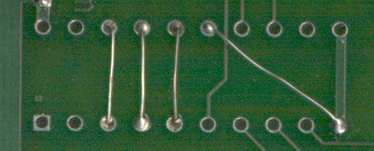
Wire strapping in place of GAL
-
Modified 26pin connector pin usage
| 2
| 4
| 6
| 8
| 10
| 12
| 14
| 16
| 18
| 20
| 22
| 24
| 26
|
| A1
| A3
| IOR
| D0
| D2
| D4
| D6
|
|
|
|
| 3.3V
| GND
|
| A0
| A2
| RST
| IOW
| D1
| D3
| D5
| D7
|
|
|
| 3.3V
| GND
|
| 1
| 3
| 5
| 7
| 9
| 11
| 13
| 15
| 17
| 19
| 21
| 23
| 25
|
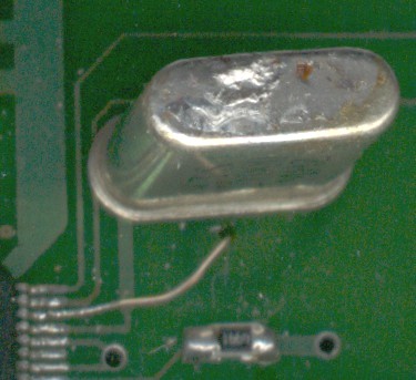
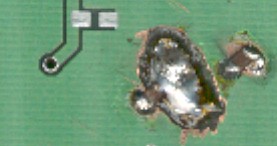
Modified PCB to replace oscillator with crystal. One
pin of the 14 pin crystal socket was reused another was drilled 0.2"
away to take the other lead of the crystal. A second hole was drilled
beside this hole and some wirewrap wire used to connect to pin 98 of the
cs8900 - this is a delicate operation. Finally a circle was ground
around the two new holes to isolate the crystal from the backplane. A
pair of 10pF ceramic SMD capacitors was then soldered between the backplane
and either pin of the crystal. Future PCBs may have support for a
crystal and the capacitors.